
Layer standards are one of those things that seem boring until you do not have them. Then they become the most important thing in your entire CAD workflow. Because without a layer standard, every drawing is a gamble. Will the cut geometry be on the right layer? Will the dimensions be separate from the contour lines? Will the file import cleanly into the CAM software? You do not know until you open it, and by then you are already spending time on cleanup instead of production.
I have worked in shops where layer standards were well-defined and enforced, and I have worked in shops where every drafter had their own system (or no system at all). The difference in downstream efficiency is not small. It is massive. A good layer standard saves hours per week in a busy shop, prevents scrap, and makes collaboration between departments—and between companies—actually functional.
This article is a practical guide to setting up a layer standard for manufacturing. Not theory, not a standards committee whitepaper—just what works in a real shop environment where drawings go from AutoCAD to laser cutters, CNC routers, waterjets, and press brakes.
Why Layer Standards Exist
Before we get into the specifics, let me explain why layers matter at all. If you are already sold on layer standards and just want the setup, skip ahead to the next section. But if you have ever wondered why you cannot just draw everything on one layer and call it done, this is for you.
Downstream Software Reads Layers
When a drawing leaves AutoCAD and enters CAM software—SigmaNEST, ProNest, Lantek, BobCAD, whatever your shop uses—the software needs to know what is cut geometry and what is not. It determines this by reading layers. Entities on the designated cut layer become toolpaths. Entities on other layers are either processed differently (etching, scoring) or ignored entirely.
Without layers, the CAM software has to guess. And software that guesses makes mistakes. Dimension text becomes a cut path. Construction lines become contours. The result is scrap parts and wasted time.
Collaboration Requires Shared Conventions
The moment more than one person touches a drawing, you need a shared understanding of what things mean. If Drafter A puts cut geometry on a layer called "CUT" with color red, and Drafter B puts cut geometry on a layer called "OUTLINE" with color blue, anyone who opens either drawing has to figure out the convention before they can work with it. This guessing game multiplies with every drafter, every vendor, and every project.
A layer standard eliminates the guessing. When every drawing follows the same convention, anyone can open any file and immediately understand its structure.
Regulatory and Client Requirements
Some industries have formal CAD standards that clients or regulations require. Government contracts often reference the National CAD Standard (NCS). Architecture firms follow AIA layering conventions. If you work in these spaces, layer compliance is not optional—it is a contractual obligation.
Even in manufacturing, where formal standards are less common, major customers often specify how they want drawings delivered. Automotive OEMs, aerospace primes, and large fabrication houses frequently have drawing delivery standards that include layer naming requirements.
Anatomy of a Good Layer Standard
A layer standard has four components: naming conventions, color assignments, linetype assignments, and lineweight rules. Let me walk through each one.
Naming Conventions
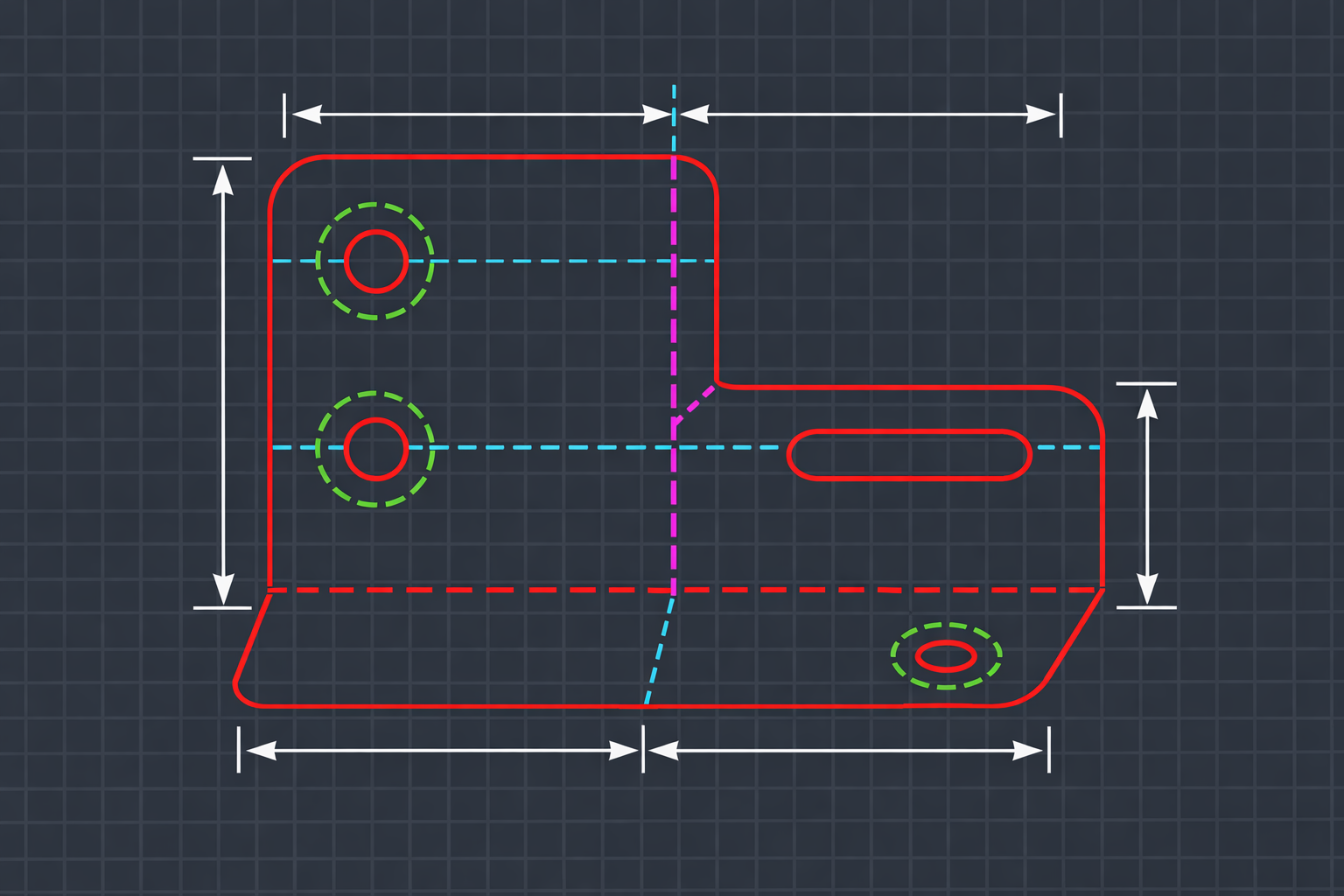
Layer names should be short, descriptive, and consistent. Here is a manufacturing-focused layer set that covers the needs of most fabrication shops:
- CUT — Primary cut/contour geometry. This is the stuff the laser actually cuts.
- ETCH — Geometry to be surface-marked (part numbers, logos, identifier marks)
- SCORE — Score lines for folding (if applicable to your process)
- BEND — Bend lines for sheet metal, showing where the brake press folds
- DIMS — All dimensions, including leaders, extension lines, and dimension text
- TEXT — Notes, callouts, part numbers, revision text—anything that is annotation
- HATCH — Cross-section hatching, fill patterns, material indicators
- CENTERLINE — Centerlines, center marks, symmetry lines
- CONSTRUCTION — Reference geometry, layout lines, anything that was used during design but is not part of the final output
- BORDER — Title block, border lines, drawing frame
Some shops add more layers for specific needs: WELD for weld symbols, HARDWARE for fastener callouts, PHANTOM for phantom lines showing adjacent parts. The principle is the same—each layer represents a distinct category of information that may need to be treated differently downstream.
A few rules for naming:
- Use ALL CAPS. It is easier to read in the layer manager and avoids case sensitivity issues.
- No spaces. Use underscores if you need a separator (BEND_UP, BEND_DOWN).
- Keep names under 20 characters. Long names get truncated in the layer dropdown and are harder to type at the command line.
- Use a prefix if you want to group layers. Some shops use "MFG_CUT", "MFG_DIMS", etc. This keeps manufacturing layers grouped alphabetically and separate from any other layers in the drawing.
Color Assignments
Color is not just aesthetic—it is functional. In AutoCAD, color often determines pen weight when plotting, and it serves as the primary visual indicator of which layer an entity is on. Here is a common color scheme for manufacturing:
- CUT — Red (Color 1). The most important layer gets the most visible color.
- ETCH — Green (Color 3). Clearly different from cut, easily distinguished.
- SCORE — Cyan (Color 4). Light colored, suggests lighter processing.
- BEND — Magenta (Color 6). Distinct from all cut-related colors.
- DIMS — White (Color 7). Standard for annotation on dark backgrounds.
- TEXT — Yellow (Color 2). Stands out for notes and callouts.
- HATCH — Color 8 (dark gray). Recedes visually, does not compete with cut geometry.
- CENTERLINE — Color 5 (blue). Traditional color for centerlines.
- CONSTRUCTION — Color 9 (light gray). Fades into background, signals "reference only."
- BORDER — Color 8 (dark gray). Background element, not the focus.
The specific colors matter less than the consistency. Pick a scheme, document it, and stick with it. What you do not want is a drawing where red means CUT for one drafter and CENTERLINE for another.
Linetype Assignments
Linetypes reinforce the visual distinction between layers:
- CUT — Continuous. Solid lines for solid cuts.
- CONSTRUCTION — Dashed or PHANTOM. Clearly different from real geometry.
- CENTERLINE — CENTER. The standard long-short-long pattern.
- BEND — DASHDOT or a custom bend linetype.
- Everything else — Continuous is fine for dims, text, hatch, border.
Lineweight Rules
Lineweight is most relevant for plotting, but it also provides visual hierarchy on screen if you have lineweight display turned on:
- CUT — Heavy (0.50mm or higher). The cut contour should be the most prominent thing on the drawing.
- DIMS, TEXT — Medium (0.25mm). Readable but not dominant.
- CENTERLINE, CONSTRUCTION — Thin (0.13mm). Background information.
- BORDER — Heavy for the outer frame, thin for the title block grid lines.
Common Industry Standards
If you are starting from scratch, it helps to know what other people use. Here are the major standards you will encounter:
National CAD Standard (NCS)
The NCS is the US standard for CAD drawing organization. It covers layer naming, sheet organization, plotting guidelines, and more. The layer naming format is discipline-major group-minor group (e.g., A-WALL-FULL for architecture, wall, full height). NCS is widely used in AEC (architecture, engineering, construction) but less common in manufacturing.
AIA Layer Guidelines
The American Institute of Architects publishes layer guidelines that are essentially the AEC subset of NCS. If you work in architectural fabrication—metal curtain walls, structural steel, ornamental metalwork—you may need to follow AIA conventions for your client deliverables.
Company-Specific Standards
In practice, most manufacturing shops use their own standard. It might be based on NCS loosely, or it might be something the CAD manager developed ten years ago that has been passed down through template files. The important thing is not which standard you follow, but that everyone follows the same one.
Setting Up Layer Templates in AutoCAD
Once you have decided on your layer standard, you need to embed it in a template so every new drawing starts with the correct layers already defined.
Creating a DWT Template
Open a new blank drawing. Set up all your standard layers using the LAYER command (or the layer manager panel). For each layer, define the name, color, linetype, lineweight, and plot style. Also set up:
- Your title block on the BORDER layer
- Any standard text styles (dimension text, note text)
- Dimension styles with the correct settings for your shop
- The current layer set to CUT (or whatever your default working layer is)
- Model space and layout tabs configured for your standard sheet sizes
Save this file as a .DWT (drawing template) file. Put it in a network location that every drafter can access. Set it as the default template in AutoCAD options so every new drawing starts from this base.
Layer States for Different Outputs
Layer states let you save and restore specific layer configurations. This is useful for creating different output scenarios:
- FOR_SHOP — CUT, ETCH, BEND visible; DIMS, TEXT, CONSTRUCTION frozen. This is what goes to the CAM programmer.
- FOR_PRINT — All layers visible. This is the full drawing with dimensions and notes for the shop traveler.
- FOR_CHECK — All layers visible with different colors optimized for on-screen review.
Create these layer states in your template so drafters can switch between them with a single click instead of manually freezing and thawing layers every time they export.
Enforcing Standards Across a Team
This is where it gets hard. Setting up a template is the easy part. Getting every drafter, every vendor, and every incoming file to follow that template? That is a different problem entirely.
The Human Problem
You write the standard. You create the template. You send the email. You even do a lunch-and-learn presentation. And then, two weeks later, you open a drawing and find dimensions on the CUT layer, construction geometry floating on Layer 0, and three new layers that someone invented because they "needed" them.
This is not a training problem. It is a systems problem. Humans forget rules when they are focused on the task at hand. A drafter who is deep in the geometry of a complex part is not thinking about which layer is current. They are thinking about the geometry. The layer mistake is unintentional and invisible to them in the moment.
Vendor Files Break Everything
Even if your internal team follows the standard perfectly, vendor files will not. Every vendor has their own convention (or no convention). You will receive files with layers named "Layer1", "DEFPOINTS", random numbers, foreign language names, and every combination imaginable. You will receive files with everything on Layer 0. You will receive files with 47 layers when you only need 9.
This means that every incoming vendor file needs to be normalized to your standard before it can enter your workflow. And doing that by hand, as I discussed in my article on cleaning up vendor AutoCAD drawings, takes 30 to 60 minutes per file.
The CAD Manager's Dilemma
If you are a CAD manager, you face a choice: spend your time policing layer compliance manually (which is not a good use of an experienced person's time), or accept that compliance will be inconsistent (which creates downstream problems). Neither option is great.
What you really want is automated enforcement—something that checks layer assignments the same way a spell-checker checks spelling, catching errors that humans miss without requiring a human to do the checking.
Automated Layer Enforcement
This is the gap that LayerGuard fills. Instead of relying on drafters to remember layer assignments and CAD managers to manually audit drawings, LayerGuard automates the enforcement.
For internal drawings, it works as a compliance check. Run it on a drawing before it leaves the department, and it reports any entities that are on the wrong layer. Dimensions on CUT? Flagged. Text on Layer 0? Flagged. Construction geometry on a non-standard layer? Flagged. The drafter fixes the flagged issues and the drawing goes out clean.
For incoming vendor drawings, LayerGuard’s RebuildToStandard mode does something more ambitious: it takes a drawing with any layer structure (or no layer structure) and normalizes it to a standard set of layers. Every entity gets classified based on its type and properties and assigned to the appropriate standard layer. A drawing that arrives with 47 random layers or everything on Layer 0 gets reorganized into a clean, predictable structure.
The result is that every drawing in your workflow—whether it was created internally or received from a vendor—follows the same layer convention. The CAM programmer does not have to guess what "Layer_47_copy(2)" contains. The drafter downstream does not have to figure out which of the vendor's 30 layers maps to which of your 9 layers. Everything is consistent.
Making Your Standard Stick
Based on my experience, here is what actually works for getting a layer standard adopted and maintained:
Keep It Simple
The more layers your standard has, the harder it is to follow. Start with the minimum set that covers your manufacturing needs. You can always add layers later if a genuine need arises. But starting with 40 layers because "we might need them someday" guarantees that nobody will remember which is which.
Document It in One Page
Your layer standard document should be one page. A table with layer name, color, linetype, lineweight, and a brief description. Post it next to every workstation. If it takes more than 30 seconds to look up where something goes, the standard is too complicated.
Embed It in the Template
The standard should live in the DWT template, not just on a piece of paper. When a drafter creates a new drawing, the layers should already be there. Zero setup required.
Check Early, Check Often
Do not wait until the drawing is at the laser to discover a layer problem. Build a check into the workflow as early as possible—ideally before the drawing leaves the drafter’s desk. Whether that is a manual checklist, a LayerGuard audit, or a peer review, the earlier you catch a problem, the cheaper it is to fix.
Handle Vendor Files Separately
Do not try to make vendors follow your standard. Some will, most will not. Instead, build a normalization step into your receiving process. When a vendor file arrives, it goes through cleanup and standardization before it enters the regular workflow. This keeps your internal standard intact even when external files do not comply.
Layer Standards Are Infrastructure
I think of layer standards the way I think of road markings. Nobody gets excited about painting lines on a road. But without them, every intersection is chaos. Every lane change is a negotiation. Every merge is a gamble.
Layer standards are the road markings of your CAD workflow. They tell everyone—drafters, programmers, machines—where things go and what they mean. They prevent the chaos that happens when every drawing is organized differently. They make it possible for files to move between people and between software without losing their meaning.
Set up the standard. Embed it in your templates. Enforce it with automation where you can. And stop treating layer assignment as optional housekeeping—it is the foundation that everything else depends on.