
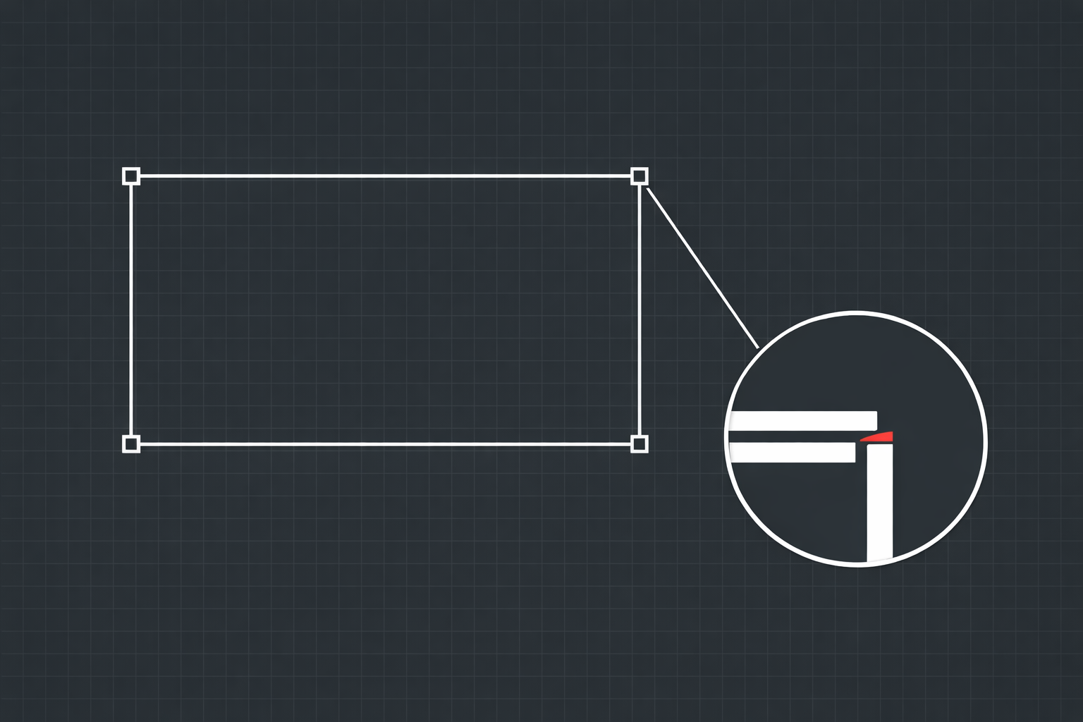
Everything looks connected. You zoomed in. The two lines overlap perfectly. The endpoints are right on top of each other. You would bet money that boundary is closed.
Then you try to hatch it and AutoCAD tells you the boundary is open.
You zoom in more. Still looks fine. You zoom in again, past the point where the pixels start getting blocky. Still looks fine. So you zoom in one more time, all the way to the limit of what the viewport can display, and the two endpoints are still sitting on top of each other.
But they are not. They are 0.00004 units apart. And that is enough for AutoCAD to consider the boundary open.
Welcome to micro-gaps.
What Exactly Is a Micro-Gap?
A micro-gap is a gap between two drawing entities that is smaller than the display resolution of your screen. It exists in the mathematical coordinates of the drawing but cannot be seen visually at any zoom level. You are looking at two points that appear identical, but when you query their actual coordinates, they differ by some tiny amount, typically below 0.001 units.
To put that in perspective, if your drawing is in inches, a 0.0001-inch gap is about the thickness of a single strand of spider silk. If your drawing is in millimeters, a 0.001mm gap is roughly one-fiftieth the diameter of a human hair. Your monitor cannot render that difference. Your eyes cannot see it even if it could. But AutoCAD's math engine sees it perfectly clearly, and it treats that gap exactly the same as a gap you could drive a truck through.
As far as AutoCAD is concerned, a boundary is either closed or it is not. There is no "close enough." Two points are either coincident or they are not. And when the gap is 0.00004 units, they are not coincident, and the boundary is open, and the hatch fails, and you start questioning your sanity.
How Micro-Gaps Get Created
The frustrating thing about micro-gaps is that you almost never create them on purpose. They sneak into your drawing through operations that feel completely normal. Here are the most common culprits.
Snap Misses During Drawing
You are drawing a line and you snap to what you think is the endpoint of another line. The ENDPOINT osnap fires, the cursor jumps, and you click. But every once in a while, especially when you are moving quickly or when multiple snap points are close together, the snap catches a different point than you intended. Maybe it grabbed the NEAREST point on the line instead of the ENDPOINT. Maybe it snapped to an INTERSECTION with a construction line that was 0.0002 units off from where you expected. The result looks correct on screen but the coordinates are slightly wrong.
This is more common than most people think. It happens most often at dense intersections where multiple entities meet, or when you are snapping to entities on different layers that overlap visually but are not geometrically identical.
Precision Loss During Transformations
Copy, rotate, mirror, and scale operations all involve math. And floating-point math has inherent precision limits. When you rotate an entity by 30 degrees, AutoCAD computes the sine and cosine of 30 degrees and multiplies them by the entity's coordinates. Those trigonometric values are irrational numbers that get truncated to fit the available precision. Each transformation introduces a tiny rounding error.
One rotation might shift a coordinate by 0.000000001 units. That is nothing. But chain five or six transformations together, copy the result to a new location, mirror it, rotate it again, and those tiny errors accumulate. After enough operations, what was once a perfectly aligned endpoint now sits 0.0003 units away from where it should be.
This is especially common in drawings with rotational symmetry where the same geometry gets copied and rotated multiple times. Each copy carries slightly different precision errors.
Unit Conversion Rounding
When you convert a drawing from imperial to metric or vice versa, every coordinate gets multiplied by a conversion factor. Going from inches to millimeters multiplies everything by 25.4. Going from millimeters to inches divides by 25.4. That division is where the trouble starts.
25.4 does not divide evenly into most coordinate values. A perfectly clean coordinate of 100mm becomes 3.93700787401... inches, which gets truncated at whatever precision AutoCAD is carrying internally. When the drawing gets converted back to metric, or when metric entities are brought into an imperial drawing, those truncated values create tiny misalignments at connection points.
DXF and DWG Import/Export Truncation
DXF files store coordinates as text strings, and the precision of those strings depends on the software that wrote the file. Some applications export DXF with six decimal places. Others use eight. Some use four. When a drawing round-trips through DXF export and import, any coordinates that exceeded the export precision get silently truncated.
A line endpoint at 5.12345678 inches gets exported as 5.123457 in a six-decimal DXF. When that file gets imported back into AutoCAD, the endpoint is now 0.00000078 inches away from where it started. At every connection point in the drawing, this tiny shift can create a micro-gap.
The same thing happens with DWG files that pass through third-party translators or older versions of AutoCAD with different internal precision.
Symptoms: How Micro-Gaps Manifest
Micro-gaps do not announce themselves. They hide until you try to do something that requires boundary closure or endpoint connectivity. Here are the operations that expose them.
Hatch Failures
This is the most common symptom and usually the first one people encounter. You select what appears to be a closed boundary, apply a hatch pattern, and get "Unable to determine valid boundary" or the hatch simply does not appear. The boundary looks closed. It is not.
You can sometimes work around this by increasing the hatch gap tolerance, but that is a band-aid. It does not fix the underlying geometry problem, and it can cause hatches to bridge gaps you did not intend, especially in dense drawings with multiple boundaries close together.
PEDIT JOIN Skips a Segment
You select 48 line segments and run PEDIT JOIN. It joins 47 of them. One segment refuses to connect, but you cannot tell which one or why. The gap is too small to see, so you start zooming around the entire boundary looking for the break. Twenty minutes later, you still have not found it.
PEDIT JOIN uses a fuzz distance to determine which endpoints are close enough to join. The default fuzz distance is usually 0.0000 or very small. If the micro-gap exceeds that distance, the join fails for that segment. You can increase the fuzz distance, but again, that risks joining things that should not be joined.
OFFSET Produces Unexpected Results
Offsetting a polyline that contains a micro-gap can produce bizarre results. The offset might create a gap in the offset geometry. It might generate a spike or a self-intersection where the gap is. It might fail entirely with an error. The behavior depends on the size and location of the micro-gap relative to the offset distance.
FILLET Does Nothing
You select two lines that appear to meet at a corner. You run FILLET with a radius. Nothing happens. Or AutoCAD says the objects do not intersect. If the endpoints of those two lines are micro-gapped, they do not actually meet, and FILLET cannot find the intersection point to create the arc.
CAM Software Rejects the Contour
This is where micro-gaps get expensive. You export a drawing to your CAM software for toolpath generation. The CAM software expects closed contours for profile cuts. It finds a micro-gap, rejects the contour, and the machine operator has to either fix it manually in the CAM system or send it back to the drafter. If the operator does not notice and tries to run it anyway, the toolpath breaks at the gap location, the cutting head lifts, and you get a witness mark or an incomplete cut.
Finding Micro-Gaps Without a Tool
The manual approach to finding micro-gaps is painful but worth understanding because it shows you exactly what the problem is.
Pick the first entity at the suspected gap location. Run the LIST command. Look at the endpoint coordinates. Write them down. Now pick the second entity. Run LIST again. Look at the endpoint coordinates that should match the first entity's endpoint. Compare them.
If entity A ends at (5.00012345, 10.00000000) and entity B starts at (5.00012348, 10.00000002), you have a micro-gap. The X coordinates differ by 0.00000003 and the Y coordinates differ by 0.00000002. The total gap distance is about 0.000000036 units. You will never see that on screen, but AutoCAD sees it.
Now imagine doing this for every connection point in a complex drawing with hundreds of entities. That is not a review process; it is a punishment. You would spend hours checking coordinates and still might miss one because you got tired or lost your place.
Some people try using PEDIT JOIN with increasingly large fuzz distances until everything connects, then check the result. This works in simple cases but can create problems in complex geometry where a large fuzz distance joins entities across boundaries that should be separate.
Automated Micro-Gap Detection
The manual LIST-and-compare method does work, but nobody wants to do it. This is exactly the kind of problem that automation solves well. The rules are clear: find every pair of endpoints that are close to each other but not coincident, measure the distance, and report the ones that fall below a threshold.
GapDetector was built specifically to handle this. It scans every entity in the drawing, catalogs all endpoints and connection points, and computes the distances between nearby endpoints. When it finds a gap below the display threshold, essentially one that you cannot see by zooming in, it flags it as a micro-gap and provides the exact coordinates, the gap distance, and a confidence score indicating how likely the gap is to cause problems.
The confidence scoring is important because not every micro-gap matters equally. A micro-gap on a contour that needs to be a closed boundary for hatching or toolpath generation is critical. A micro-gap on a construction line that is only there for reference is cosmetic. The severity classification helps you focus on the gaps that will actually cause problems, rather than fixing every sub-tolerance imperfection in the drawing.
The scan runs across the entire drawing, which matters because micro-gaps can appear anywhere, not just in the areas you suspect. You might have a micro-gap on a boundary that you have never tried to hatch yet. It will not cause a problem until someone does try to hatch it, and by then the drawing might be in production and the fix costs ten times more than it would have during drafting.
Prevention: Keeping Micro-Gaps Out of Your Drawings
Finding and fixing micro-gaps is important, but preventing them in the first place is better. Here are the practices that reduce micro-gap creation.
Always Use ENDPOINT Osnap
When connecting to existing geometry, use ENDPOINT, not NEAREST. NEAREST snaps to the closest point on the entity, which might be very close to the endpoint but not exactly on it. ENDPOINT always gives you the exact coordinate of the line or arc end. Make ENDPOINT your default running osnap. If you need NEAREST for a specific operation, turn it on temporarily and turn it off immediately after.
Set SNAPANG to 0
A non-zero snap angle rotates the entire snap grid, which means coordinates that were clean at 0 degrees become irrational at other angles. Unless you specifically need a rotated snap grid, keep SNAPANG at 0. This keeps your coordinates on clean values that are less susceptible to precision loss during transformations.
Increase Unit Display Precision
Set your display precision to 8 decimal places using the UNITS command. This does not change the internal precision of the drawing; AutoCAD always works at full double-precision floating-point internally. But it does let you see more of the actual coordinate values when using LIST or inspecting properties, making it easier to spot coordinates that are not where you expected.
Minimize Transformation Chains
Every copy-rotate-mirror-scale operation introduces tiny rounding errors. When possible, draw geometry directly in its final position instead of drawing it somewhere else and moving it. If you must transform geometry, try to do it in a single operation rather than a sequence of individual transforms. Rotating once by 90 degrees introduces less error than rotating three times by 30 degrees.
Be Careful with Unit Conversions
If you work in both metric and imperial, decide on a master unit system for each project and stick with it. Every conversion between systems introduces potential precision loss. If you receive a file in the other unit system, convert it once at the beginning and work in the converted units from that point forward. Do not keep converting back and forth.
Audit After Imports
Any time you import geometry from an external source, whether it is a DXF from a client, a DWG from a subcontractor, or geometry pasted from another drawing, run a gap check on the imported area before integrating it into your work. The import is where precision loss is most likely, and catching it immediately is far cheaper than finding it during manufacturing.
The Real Cost of Ignoring Micro-Gaps
Micro-gaps are easy to dismiss because they are literally invisible. But the problems they cause are not. A hatch failure during drafting costs five minutes. A rejected contour in CAM costs an hour. A broken toolpath on the machine costs material, time, and potentially a scrapped part.
The CAD manager who says "we have never had a problem with micro-gaps" probably has. They just did not know the root cause. That hatch that "randomly" would not work? Probably a micro-gap. That PEDIT JOIN that kept skipping one segment? Almost certainly a micro-gap. That CAM rejection that the operator "fixed" by healing the contour? Definitely a micro-gap, and the operator's fix may have shifted geometry by more than the original gap.
You do not have to become paranoid about this. You do have to have a process for catching it. Run a gap detection scan as part of your drawing QA workflow, particularly on drawings that go to manufacturing and on anything that came from an external source. It takes seconds and it catches the things you cannot see.
The endpoints might look like they are touching. The coordinates say otherwise. Trust the coordinates.